Free practice test
Try 30 questions free
Work through 30 questions, then see your score, results by topic and an explanation for every answer. No account or email needed.
These are 30 of the 150 questions in the full PDF. You can also read the questions and answers below.
The full 150-question PDF
Includes the 30 free questions plus 120 additional questions, explanations and references. One payment, no subscription.
| Questions | 150, all original |
|---|---|
| Answer key | Correct answer, the reasoning, and a cited source for each question |
| Distinct references | 38 distinct citations across the bank |
| Free samples here | 30, with answers, below |
| Format | PDF, emailed on purchase, plus a download link valid 30 days |
| Price | $67.49 CAD, one payment, no subscription |
Payment is handled by Stripe. This is study material, not an official exam, and it is not affiliated with Skilled Trades Ontario, TSSA or the Red Seal program.
Look inside the PDF
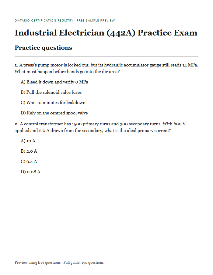
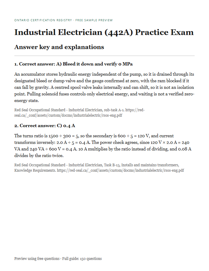
A preview of the question and answer-key layout, using questions from the free sample. The full guide contains all 150 questions.
What this guide covers
Published Red Seal exam activity counts scaled from 100 to 150 with whole-question rounding. The 150-question allocation uses the published 9/23/20/21/10/17 counts and assigns the two rounding questions to activities A and B; those rounded counts total 150. The bank cognitive mix falls within the published ranges. This is an independent practice bank, not an official examination. The table shows the actual counts and shares in this guide.
| Major work activity | Questions here | Share of this guide |
|---|---|---|
| A. Performs common occupational skills | 14 | 9.3% |
| B. Installs and maintains generating, distribution and service systems | 35 | 23.3% |
| C. Installs and maintains wiring systems | 30 | 20% |
| D. Installs and maintains rotating and non-rotating equipment and control systems | 31 | 20.7% |
| E. Installs and maintains signalling and communication systems | 15 | 10% |
| F. Installs and maintains process control systems | 25 | 16.7% |
The published official exam has 100 questions. This guide contains 150 original study questions, with topic counts rounded to fit that length.
Coverage source: Published Red Seal exam breakdown
The mix of question types
The table compares this guide's mix with the published Red Seal ranges for this trade.
| Type | Questions here | Share | Published range |
|---|---|---|---|
| Knowledge and recall | 18 | 12% | 10 to 20% |
| Procedural and application | 67 | 44.7% | 35 to 45% |
| Critical thinking | 65 | 43.3% | 40 to 50% |
30 free sample questions from the Industrial Electrician (442A) bank
This fixed selection comes straight from the bank and covers every major work activity, with the answers and sources shown. Read them before you decide whether the rest is worth $67.49 to you.
Question 1: A press's pump motor is locked out, but its hydraulic accumulator gauge still reads 14 MPa. What must happen before hands go into the die area?
Sample 1 · Activity A
A press's pump motor is locked out, but its hydraulic accumulator gauge still reads 14 MPa. What must happen before hands go into the die area?
- Bleed it down and verify 0 MPa (correct)
- Pull the solenoid valve fuses
- Wait 10 minutes for leakdown
- Rely on the centred spool valve
An accumulator stores hydraulic energy independent of the pump, so it is drained through its designated bleed or dump valve and the gauge confirmed at zero, with the ram blocked if it can fall by gravity. A centred spool valve leaks internally and can shift, so it is not an isolation point. Pulling solenoid fuses controls only electrical energy, and waiting is not a verified zero-energy state.
Red Seal Occupational Standard - Industrial Electrician, sub-task A-1. https://red-seal.ca/_conf/assets/custom/docms/industrialelectric/rsos-eng.pdf
Question 2: An area drawing classifies a solvent room as Class I, Zone 1 (flammable gas or vapour). A replacement motor is marked only Class II, Division 1 (combustible dust). What should be concluded?
Sample 2 · Activity A
An area drawing classifies a solvent room as Class I, Zone 1 (flammable gas or vapour). A replacement motor is marked only Class II, Division 1 (combustible dust). What should be concluded?
- Suitable: Division 1 is stricter
- Suitable if its T-code is lower
- Unsuitable for this atmosphere (correct)
- Unsuitable: Zone 0 is required
Hazardous-location equipment must be marked for the class of hazard present, and a dust rating says nothing about containing a gas or vapour ignition. Comparing Division 1 with Zone 1 matters only within the same class, so the stricter-sounding division does not help. A suitable temperature code is needed in addition to the right class, and a Zone 1 area does not require Zone 0 equipment.
Red Seal Occupational Standard - Industrial Electrician, sub-task A-3. https://red-seal.ca/_conf/assets/custom/docms/industrialelectric/rsos-eng.pdf
Question 3: A 600 V drawout power circuit breaker with a motor-charged operating mechanism is fully withdrawn for service. What hazardous energy can remain in it?
Sample 3 · Activity A
A 600 V drawout power circuit breaker with a motor-charged operating mechanism is fully withdrawn for service. What hazardous energy can remain in it?
- Residual bus voltage
- Its control-power voltage
- Charge stored in its CTs
- A charged closing spring (correct)
Power breakers store closing energy in a spring that a motor or hand lever charges, and it stays charged after the breaker is withdrawn; a close or trip operation can release it violently, so the springs are discharged as the maker's instructions direct before work on the mechanism. Full withdrawal separates the primary stabs from the bus and the secondary contacts from control power. A CT stores no energy once its primary carries no current.
Red Seal Occupational Standard - Industrial Electrician, sub-task A-1. https://red-seal.ca/_conf/assets/custom/docms/industrialelectric/rsos-eng.pdf
Question 4: A control transformer has 1500 primary turns and 300 secondary turns. With 600 V applied and 2.0 A drawn from the secondary, what is the ideal primary current?
Sample 4 · Activity B
A control transformer has 1500 primary turns and 300 secondary turns. With 600 V applied and 2.0 A drawn from the secondary, what is the ideal primary current?
- 10 A
- 2.0 A
- 0.4 A (correct)
- 0.08 A
The turns ratio is 1500 ÷ 300 = 5, so the secondary is 600 ÷ 5 = 120 V, and current transforms inversely: 2.0 A ÷ 5 = 0.4 A. The power check agrees, since 120 V × 2.0 A = 240 VA and 240 VA ÷ 600 V = 0.4 A. 10 A multiplies by the ratio instead of dividing, and 0.08 A divides by the ratio twice.
Red Seal Occupational Standard - Industrial Electrician, Task B-15, Installs and maintains transformers, Knowledge Requirements. https://red-seal.ca/_conf/assets/custom/docms/industrialelectric/rsos-eng.pdf
Question 5: A feeder sub-meter is programmed for 200:5 CTs, but the installed CTs are stamped 400:5. The meter shows 150 kW. What is the actual load?
Sample 5 · Activity B
A feeder sub-meter is programmed for 200:5 CTs, but the installed CTs are stamped 400:5. The meter shows 150 kW. What is the actual load?
- 75 kW
- 600 kW
- 150 kW
- 300 kW (correct)
The meter multiplies secondary current by the programmed ratio of 40 instead of the real 80, so it reads half the true value: 150 kW × 80 ÷ 40 = 300 kW. 75 kW applies the correction backwards, and 600 kW squares the ratio error. Correct the programmed ratio, then confirm against a clamp reading on the primary conductors.
Red Seal Occupational Standard - Industrial Electrician, sub-task B-7. https://red-seal.ca/_conf/assets/custom/docms/industrialelectric/rsos-eng.pdf
Question 6: In a standard moulded-case circuit breaker, which part trips it on a sustained 125% overload?
Sample 6 · Activity B
In a standard moulded-case circuit breaker, which part trips it on a sustained 125% overload?
- The shunt trip coil
- The arc chute stack
- The magnetic element
- The bimetal element (correct)
The bimetal heats with current over time and bends to trip on sustained overloads, giving the inverse-time part of the trip curve. The magnetic element responds almost instantly to fault currents many times the rating and does not react to 125%. A shunt trip is a remote-trip coil, and the arc chutes only quench the arc after the contacts part.
Red Seal Occupational Standard - Industrial Electrician, sub-task B-8. https://red-seal.ca/_conf/assets/custom/docms/industrialelectric/rsos-eng.pdf
Question 7: A CT-connected sub-meter must be removed while its feeder stays loaded. What must be done to the CT secondaries first?
Sample 7 · Activity B
A CT-connected sub-meter must be removed while its feeder stays loaded. What must be done to the CT secondaries first?
- Lift the secondary ground
- Open them at the test block
- Fuse each secondary lead
- Short them at the test block (correct)
A CT forces its secondary current through whatever is connected, so opening the secondary under load produces a very high voltage that can arc, injure and damage the CT; shorting it at the test switch or shorting block keeps the circuit closed while the meter is out. Voltage-transformer secondaries are fused, but CT secondaries are not, because a blown fuse would open the circuit. The single secondary ground stays connected.
Red Seal Occupational Standard - Industrial Electrician, sub-task B-7. https://red-seal.ca/_conf/assets/custom/docms/industrialelectric/rsos-eng.pdf
Question 8: A motor ran at 62 A until its feeder trip unit was replaced. Now set at 80 A long-time and 4× instantaneous, it trips within a cycle at every start. Locked-rotor current is 410 A. What is the cause?
Sample 8 · Activity B
A motor ran at 62 A until its feeder trip unit was replaced. Now set at 80 A long-time and 4× instantaneous, it trips within a cycle at every start. Locked-rotor current is 410 A. What is the cause?
- Instantaneous pickup too low (correct)
- Supply phase loss at start
- Winding fault to ground
- Long-time pickup too low
The instantaneous pickup is 4 × 80 A = 320 A, below the 410 A locked-rotor current and the higher first-cycle peak, so it trips on inrush. The long-time element at 80 A sits above the 62 A running current and would take seconds, not a cycle, to act, and the problem began with the trip-unit change rather than the motor. Change settings only from the coordination study and motor data.
Red Seal Occupational Standard - Industrial Electrician, sub-task B-8. https://red-seal.ca/_conf/assets/custom/docms/industrialelectric/rsos-eng.pdf
Question 9: A 208Y/120 V system feeds many single-phase computer power supplies. Which harmonic currents add in the shared neutral instead of cancelling?
Sample 9 · Activity B
A 208Y/120 V system feeds many single-phase computer power supplies. Which harmonic currents add in the shared neutral instead of cancelling?
- 11th and 13th harmonics
- Triplens: 3rd, 9th, 15th (correct)
- Even: 2nd, 4th, 6th
- 5th and 7th harmonics
Triplen harmonics, the odd multiples of the 3rd, are in phase in all three phases, so they add in the neutral, which can then carry more current than a phase conductor. The 5th, 7th, 11th and 13th are positive- or negative-sequence and cancel in a balanced neutral. Even harmonics are normally small because these current waveforms are symmetrical.
Red Seal Occupational Standard - Industrial Electrician, sub-task B-10. https://red-seal.ca/_conf/assets/custom/docms/industrialelectric/rsos-eng.pdf
Question 10: A UPS DC capacitor bank of 4700 µF is charged to 600 V and discharges through a 10 kΩ bleed resistor. About what voltage remains 47 s after isolation?
Sample 10 · Activity B
A UPS DC capacitor bank of 4700 µF is charged to 600 V and discharges through a 10 kΩ bleed resistor. About what voltage remains 47 s after isolation?
- 221 V (correct)
- 4 V
- 379 V
- 300 V
The time constant is R × C = 10 000 Ω × 0.0047 F = 47 s, and after one time constant the voltage falls to about 36.8% of its start: 600 × 0.368 = 221 V. 379 V is the amount that has drained (63.2%), not what remains, and about 4 V is reached only after five time constants, roughly 235 s. Verify with a meter before contact, since a failed bleed resistor stops the discharge.
Red Seal Occupational Standard - Industrial Electrician, sub-task B-10. https://red-seal.ca/_conf/assets/custom/docms/industrialelectric/rsos-eng.pdf
Question 11: A lighting circuit must be switched from three separate doorways. Which switches are needed?
Sample 11 · Activity C
A lighting circuit must be switched from three separate doorways. Which switches are needed?
- Two 3-way and one 4-way (correct)
- Three 4-way switches
- One 3-way and two 4-way
- Three 3-way switches
The two ends of the switching run use 3-way switches, and each location in between uses a 4-way switch that crosses the two travellers. Three 3-way switches cannot provide a middle location, and a 4-way switch cannot start or end the traveller pair. Any number of locations uses two 3-ways, with 4-ways for the rest.
Red Seal Occupational Standard - Industrial Electrician, sub-task C-17. https://red-seal.ca/_conf/assets/custom/docms/industrialelectric/rsos-eng.pdf
Question 12: A thermal scan shows one 20 A breaker's load terminal at 68 °C while its neighbours sit at 31 °C. All carry about 14 A by clamp meter. What is the likely cause?
Sample 12 · Activity C
A thermal scan shows one 20 A breaker's load terminal at 68 °C while its neighbours sit at 31 °C. All carry about 14 A by clamp meter. What is the likely cause?
- Breaker rated too low
- Branch circuit overload
- Harmonics on the neutral
- High-resistance termination (correct)
Equal current in each circuit but one hot terminal points to I²R heating at a high-resistance joint: a loose, corroded or damaged connection, or the breaker's own contact. 14 A is within the 20 A rating and matches the neighbours, so overload or undersizing does not explain a single hot spot, and neutral harmonics do not heat a phase terminal. De-energize, inspect and repair to the maker's torque, then rescan under load.
Red Seal Occupational Standard - Industrial Electrician, sub-task C-17. https://red-seal.ca/_conf/assets/custom/docms/industrialelectric/rsos-eng.pdf
Question 13: What is the main purpose of an EYS fitting filled with sealing compound where a conduit leaves a hazardous location?
Sample 13 · Activity C
What is the main purpose of an EYS fitting filled with sealing compound where a conduit leaves a hazardous location?
- Drain condensed moisture
- Allow thermal expansion
- Provide a pulling point
- Limit gas and flame travel (correct)
Packed with fibre dam and poured compound, the fitting blocks gases, vapours and flame from passing through the conduit into other enclosures or areas. It is not a drain fitting (a drain-seal type adds that), an expansion fitting or a pull point, since nothing can be pulled through it once poured. Pour the compound only after the conductors are installed, following the fitting maker's instructions.
Red Seal Occupational Standard - Industrial Electrician, sub-task C-16. https://red-seal.ca/_conf/assets/custom/docms/industrialelectric/rsos-eng.pdf
Question 14: A receptacle's breaker in a 42-circuit panel is unlabelled, and no loads may be interrupted. How is its breaker found?
Sample 14 · Activity C
A receptacle's breaker in a 42-circuit panel is unlabelled, and no loads may be interrupted. How is its breaker found?
- Match the conductor colours
- Signal tracer read at the panel (correct)
- Non-contact tester at the panel
- Open each breaker in turn
A tracer transmitter plugged into the receptacle puts a signal on that circuit, and the receiver finds the breaker carrying it without switching anything off. A non-contact tester lights on every energized breaker, and conductor colours repeat across many circuits. Update the panel directory once the breaker is confirmed.
Red Seal Occupational Standard - Industrial Electrician, sub-task C-17. https://red-seal.ca/_conf/assets/custom/docms/industrialelectric/rsos-eng.pdf
Question 15: A 120 V, 20 A shop receptacle circuit trips a few minutes after an 1800 W heater and a 1500 W heater are both switched on. Each heater runs alone without tripping. What is the cause?
Sample 15 · Activity C
A 120 V, 20 A shop receptacle circuit trips a few minutes after an 1800 W heater and a 1500 W heater are both switched on. Each heater runs alone without tripping. What is the cause?
- Combined 27.5 A overload (correct)
- Ground fault in one heater
- Inrush from heater elements
- Breaker tripping below 20 A
The heaters draw 1800 ÷ 120 = 15 A and 1500 ÷ 120 = 12.5 A, so together they load the circuit to 27.5 A, about 138% of its rating, and an inverse-time breaker trips on that after a delay. A breaker that trips on a real overload is not weak, a ground fault would also show with that heater alone, and resistive elements have negligible inrush. Move one heater to another circuit rather than fitting a larger breaker.
Red Seal Occupational Standard - Industrial Electrician, sub-task C-17. https://red-seal.ca/_conf/assets/custom/docms/industrialelectric/rsos-eng.pdf
Question 16: Which light source takes several minutes to reach full output and, after a brief power dip, must cool before it will restart?
Sample 16 · Activity C
Which light source takes several minutes to reach full output and, after a brief power dip, must cool before it will restart?
- Tungsten halogen lamp
- T8 fluorescent lamp
- LED high-bay module
- Metal halide lamp (correct)
A metal halide lamp is a high-intensity discharge source: its arc tube must heat and build pressure to reach full output, and after an interruption it must cool before the ballast can restrike it. A T8 fluorescent also uses a ballast but starts within seconds and restarts at once, and LED and halogen sources light immediately. This is why HID areas are often given separate instant-on emergency or standby lighting.
Red Seal Occupational Standard - Industrial Electrician, sub-task C-17. https://red-seal.ca/_conf/assets/custom/docms/industrialelectric/rsos-eng.pdf
Question 17: Two 120 V contactor coils, each 18 VA sealed and 150 VA inrush, can pick up at the same moment while 10 VA of pilot lights are already on. What total inrush VA must the control transformer supply?
Sample 17 · Activity D
Two 120 V contactor coils, each 18 VA sealed and 150 VA inrush, can pick up at the same moment while 10 VA of pilot lights are already on. What total inrush VA must the control transformer supply?
- 346 VA
- 310 VA (correct)
- 160 VA
- 46 VA
At pickup each coil draws its inrush, not its sealed value, so the momentary load is 150 + 150 + 10 = 310 VA. 46 VA is the sealed load once the coils have closed, and 160 VA counts only one coil. Adding the sealed values on top of the inrush (346 VA) counts the same coils twice. A control transformer is chosen from the maker's inrush rating, which is published separately from its continuous VA rating.
Red Seal Occupational Standard - Industrial Electrician, sub-task D-24. https://red-seal.ca/_conf/assets/custom/docms/industrialelectric/rsos-eng.pdf
Question 18: A contactor's 120 V coil measures 120 V when commanded, but the armature does not move and there is no hum. A clamp meter on a coil lead reads 0 A. What is the cause?
Sample 18 · Activity D
A contactor's 120 V coil measures 120 V when commanded, but the armature does not move and there is no hum. A clamp meter on a coil lead reads 0 A. What is the cause?
- Control voltage too low
- Armature jammed in guide
- Stop button contact open
- Open circuit in winding (correct)
Full voltage across the coil with no current means its circuit is open inside the winding or at its terminations. A mechanically jammed armature leaves the magnetic gap open, so an AC coil would hum loudly and draw high current, while low control voltage or an open stop button would show as a low or zero reading at the coil. Isolate the starter, confirm the open with an ohmmeter, and replace the coil with one of the correct voltage.
Red Seal Occupational Standard - Industrial Electrician, sub-task D-22. https://red-seal.ca/_conf/assets/custom/docms/industrialelectric/rsos-eng.pdf
Question 19: What does a service factor of 1.15 on a motor nameplate indicate?
Sample 19 · Activity D
What does a service factor of 1.15 on a motor nameplate indicate?
- Runs on 115% of rated voltage
- Carries 115% of rated load (correct)
- Draws 115% of FLA at start
- Insulation rated for 115°C
At rated voltage and frequency, a 1.15 service factor means the motor can deliver 115% of its rated power continuously, at the cost of higher temperature rise and shorter insulation life. It is not a voltage tolerance, a starting-current figure (starting current is several times FLA) or an insulation temperature, which the insulation class shows. Plan normal loading at or below rated power and keep the service factor as margin.
Red Seal Occupational Standard - Industrial Electrician, sub-task D-25. https://red-seal.ca/_conf/assets/custom/docms/industrialelectric/rsos-eng.pdf
Question 20: A 120 V AC starter coil chatters when commanded. At the coil terminals it measures 84 V, while the control transformer secondary measures 121 V under the same conditions. What is the next step?
Sample 20 · Activity D
A 120 V AC starter coil chatters when commanded. At the coil terminals it measures 84 V, while the control transformer secondary measures 121 V under the same conditions. What is the next step?
- Fit a larger control transformer
- Replace the contactor coil
- Clean the contactor pole faces
- Measure drop across each contact (correct)
The transformer holds 121 V, but 121 − 84 = 37 V is lost before the coil, so the fault is resistance in the control path: a pitted pilot contact, loose terminal or failing wire. Measuring the voltage across each closed contact and connection while commanded locates it. A new coil or a larger transformer would not remove that drop, and dirty pole faces cause hum or chatter at full coil voltage, which is not the case here.
Red Seal Occupational Standard - Industrial Electrician, sub-task D-22. https://red-seal.ca/_conf/assets/custom/docms/industrialelectric/rsos-eng.pdf
Question 21: A loaded three-phase motor draws 44 A, 52 A and 45 A. After its leads are rolled one position at the motor terminals, the 52 A reading stays on the same incoming line. Where is the problem?
Sample 21 · Activity D
A loaded three-phase motor draws 44 A, 52 A and 45 A. After its leads are rolled one position at the motor terminals, the 52 A reading stays on the same incoming line. Where is the problem?
- Motor's stator winding
- Supply side of the circuit (correct)
- Broken rotor bars
- The driven mechanical load
Average current is 47 A and the largest deviation is 5 A, an unbalance of about 10.6%. Because the high current stayed on the same incoming line instead of following the motor winding to a new line, the cause lies upstream, such as voltage unbalance or a poor connection. A winding fault would move with the winding, while a mechanical load or rotor bars affect all three phases alike; measure the supply voltages next.
Red Seal Occupational Standard - Industrial Electrician, sub-task D-25. https://red-seal.ca/_conf/assets/custom/docms/industrialelectric/rsos-eng.pdf
Question 22: In a combination motor starter, which device protects the windings when the motor draws 130% of full-load current for a long period?
Sample 22 · Activity D
In a combination motor starter, which device protects the windings when the motor draws 130% of full-load current for a long period?
- Inverse-time breaker
- Overload relay (correct)
- Branch-circuit fuses
- Control-circuit fuse
The overload relay is set close to the motor's full-load current and trips on sustained running overcurrent such as 130%. Branch-circuit fuses and inverse-time breakers in a motor circuit are sized well above full-load current so the motor can start, so they clear short circuits and ground faults but let a moderate running overload continue. The control-circuit fuse protects only the control wiring and coil.
Red Seal Occupational Standard - Industrial Electrician, sub-task D-22. https://red-seal.ca/_conf/assets/custom/docms/industrialelectric/rsos-eng.pdf
Question 23: A conventional fire alarm initiating zone shows a trouble signal. With its field wiring lifted at the panel, the pair reads open circuit (OL) instead of the EOL resistor value. What is the next step?
Sample 23 · Activity E
A conventional fire alarm initiating zone shows a trouble signal. With its field wiring lifted at the panel, the pair reads open circuit (OL) instead of the EOL resistor value. What is the next step?
- Fit an EOL at the panel
- Split the circuit to find it (correct)
- Replace the EOL resistor
- Replace the zone input card
An open reading on the lifted field pair puts the fault in the wiring or devices, so the circuit is divided at device boxes and measured until the open is found. The EOL resistor is only one of many possible open points, and moving an EOL to the panel clears the trouble but leaves the field wiring unsupervised. The zone card is not suspect, because the field pair itself measures open.
Red Seal Occupational Standard - Industrial Electrician, sub-task E-26. https://red-seal.ca/_conf/assets/custom/docms/industrialelectric/rsos-eng.pdf
Question 24: A replacement 4 to 20 mA duct temperature transmitter is ranged −40 to 60 °C. Its display and a reference thermometer both read 20 °C, and the loop current measures 13.6 mA, but the BAS shows 30 °C. Where is the fault?
Sample 24 · Activity E
A replacement 4 to 20 mA duct temperature transmitter is ranged −40 to 60 °C. Its display and a reference thermometer both read 20 °C, and the loop current measures 13.6 mA, but the BAS shows 30 °C. Where is the fault?
- BAS input scaling or offset (correct)
- Temperature sensor drift
- Loop wiring resistance
- Transmitter output calibration
20 °C is (20 + 40) ÷ 100 = 60% of the range, and 4 + 0.6 × 16 = 13.6 mA, so the transmitter is sending exactly the right current. The error is in how the BAS converts that current; a range left at −30 to 70 °C from the old sensor, for example, would show 30 °C. The reference thermometer rules out sensor drift, and wiring resistance cannot shift a current that measures correctly.
Red Seal Occupational Standard - Industrial Electrician, sub-task E-28. https://red-seal.ca/_conf/assets/custom/docms/industrialelectric/rsos-eng.pdf
Question 25: Which of these is an initiating device in a fire alarm system?
Sample 25 · Activity E
Which of these is an initiating device in a fire alarm system?
- Remote annunciator panel
- Magnetic door holder
- Combination horn-strobe
- Sprinkler waterflow switch (correct)
Initiating devices send an alarm or supervisory input to the control unit, and a waterflow switch operates when water moves in the sprinkler piping. Horns and strobes are signalling devices the panel drives, an annunciator displays status, and a magnetic door holder is an associated device the panel releases. Each class is wired and supervised differently, so identifying it matters when reading fire alarm drawings.
Red Seal Occupational Standard - Industrial Electrician, sub-task E-26. https://red-seal.ca/_conf/assets/custom/docms/industrialelectric/rsos-eng.pdf
Question 26: A two-wire 4 to 20 mA pressure loop reads 0 mA at the PLC. With the loop powered, the transmitter terminals measure 24 V DC, equal to the loop supply. What is the fault?
Sample 26 · Activity F
A two-wire 4 to 20 mA pressure loop reads 0 mA at the PLC. With the loop powered, the transmitter terminals measure 24 V DC, equal to the loop supply. What is the fault?
- Transmitter open circuit (correct)
- Shorted transmitter
- Blown loop supply fuse
- Open wire at PLC input
With no current flowing, the whole supply voltage appears across whatever is open, so 24 V across the transmitter puts the open inside it. A blown fuse or an open wire elsewhere would leave about 0 V across the transmitter, and a shorted transmitter would draw high current, not none. Check its terminations, then replace it if the open is internal.
Red Seal Occupational Standard - Industrial Electrician, sub-task F-29. https://red-seal.ca/_conf/assets/custom/docms/industrialelectric/rsos-eng.pdf
Question 27: A pressure transmitter's display is steady. A milliamp clamp meter on the same loop conductor reads a steady 12.0 mA at the transmitter but 12.0 to 14.0 mA at the PLC input, where the value jumps. What is indicated?
Sample 27 · Activity F
A pressure transmitter's display is steady. A milliamp clamp meter on the same loop conductor reads a steady 12.0 mA at the transmitter but 12.0 to 14.0 mA at the PLC input, where the value jumps. What is indicated?
- Leakage in the field wiring (correct)
- Unstable transmitter output
- Pulsating process pressure
- Faulty PLC analog input
In a series loop the same current flows at every point, so extra, unsteady current at the PLC end means a path between the conductors, such as moisture or damaged insulation in a junction box, is adding current between the two measuring points. A faulty input or an unstable transmitter would change the current at both points, and a pulsating process would move the transmitter's own output. Inspect junction boxes and test the cable insulation between the two points.
Red Seal Occupational Standard - Industrial Electrician, sub-task F-29. https://red-seal.ca/_conf/assets/custom/docms/industrialelectric/rsos-eng.pdf
Question 28: Which of these is a discrete input device in a process control system?
Sample 28 · Activity F
Which of these is a discrete input device in a process control system?
- Solenoid valve
- Proportional valve
- Float level switch (correct)
- Pressure transmitter
A float switch opens or closes a contact at one set level, giving the controller an on or off input. A pressure transmitter is also an input, but an analog one that sends a continuous signal, while solenoid and proportional valves are output devices, discrete and analog respectively. The device class decides which I/O card and wiring it needs.
Red Seal Occupational Standard - Industrial Electrician, sub-task F-29. https://red-seal.ca/_conf/assets/custom/docms/industrialelectric/rsos-eng.pdf
Question 29: A stop button is wired normally closed to a PLC input, and the input is on with the button released. The rung uses an examine-off instruction for it, and the motor never starts. What is the correct fix?
Sample 29 · Activity F
A stop button is wired normally closed to a PLC input, and the input is on with the button released. The rung uses an examine-off instruction for it, and the motor never starts. What is the correct fix?
- Force the stop input off
- Rewire the stop as NO
- Add a seal-in branch
- Use examine-on for the stop (correct)
With a normally closed button the input is on while released, so an examine-off instruction is false and blocks the rung; examine-on passes while released and opens when the button is pressed or a wire breaks. Rewiring the button normally open would let the motor start, but a broken wire would then disable the stop without warning. Emergency stops must also meet hardwired safety requirements, not PLC logic alone.
Red Seal Occupational Standard - Industrial Electrician, sub-task F-30. https://red-seal.ca/_conf/assets/custom/docms/industrialelectric/rsos-eng.pdf
Question 30: A PLC relay output is on, but its 120 V AC contactor coil will not pull in. Measured to a known-good neutral, coil terminals A1 and A2 both read 120 V, and across the coil reads 0 V. What is the fault?
Sample 30 · Activity F
A PLC relay output is on, but its 120 V AC contactor coil will not pull in. Measured to a known-good neutral, coil terminals A1 and A2 both read 120 V, and across the coil reads 0 V. What is the fault?
- Open coil return path (correct)
- Open contactor coil
- Failed PLC output contact
- Open wire from PLC to A1
A1 at 120 V proves the output contact and the wire to the coil are good, and A2 also at 120 V means line potential is passing through an intact coil with no current flowing, so the return from A2 to neutral is open. That path often includes the overload contact, so check it as well as the neutral wiring. An open coil would leave A2 at 0 V and show 120 V across the coil.
Red Seal Occupational Standard - Industrial Electrician, sub-task F-30. https://red-seal.ca/_conf/assets/custom/docms/industrialelectric/rsos-eng.pdf
Before you buy
- These questions use the cited occupational standards, curriculum and technical references. Nothing here is reproduced from a real exam.
- Passing this does not guarantee passing the certifying exam, and nothing here is a substitute for the training standard or your in-school hours.
- It is a PDF. There is no login, no expiry and no subscription, and you can print it.
- Automated structure and distribution checks are complete. Technical accuracy review by a licensed tradesperson remains outstanding.
Questions about your purchase or a missing PDF? Contact Blue Crane Works with the email used at checkout. The download link lasts 30 days; your saved PDF does not expire.
When you are ready for the real exam
You book the 442A certifying exam yourself in the Skilled Trades Ontario Portal ($150 plus HST) and write it at one of 24 exam centres, or at your college in your final level of school. How to book it and find the nearest centre.
Writing in Alberta, BC or Manitoba? Same Red Seal exam
The Industrial Electrician exam is the national Red Seal exam, so this practice exam fits writers in other provinces too, wherever the trade carries the Red Seal. Trade names differ by province.
Where the exam facts on this page come from
Published Red Seal exam activity counts scaled from 100 to 150 with whole-question rounding. The 150-question allocation uses the published 9/23/20/21/10/17 counts and assigns the two rounding questions to activities A and B; those rounded counts total 150. The bank cognitive mix falls within the published ranges. This is an independent practice bank, not an official examination. The regulation and issuing authority explain the actual credential and examination requirements.
The free reference material for this trade
Everything about the certification itself, the classification, the hours, the ratio and the official sources, stays free on this site and always will. The practice exam is the only thing here that costs anything.